


113386-14 www.amdry.com 27
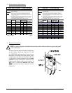
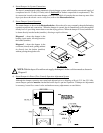
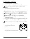
4. Steam Damper Air System Connections
The dryer is manufactured with a pneumatic (piston) damper system, which requires an external supply of
compressed air of 4.25 cfh (0.12 cmh) (refer to
Section M for further compressed air requirements). The
air connection is made to the steam damper solenoid valve which is located at the rear inner top area of the
dryer just above the electric service relay box (refer to the illustration below).
5.
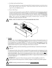
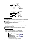
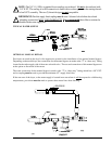
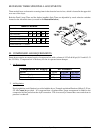
Steam Damper System Operation
The steam damper, as shown in the illustration below, allows the coil to stay constantly charged eliminating
repeated expansion and contraction. When the damper is opened, the air immediately passes through the
already hot coil, providing instant heat to start the drying process. When the damper is closed, ambient air
is drawn directly into the basket (tumbler), allowing a rapid cool down.
Diagram 1 – shows the damper in the
heating (open) mode, allowing heat into
the basket (tumbler).
Diagram 2 – shows the damper in the
cool down (closed) mode, pulling ambient
air directly into the basket (tumbler)
without passing through the coils.
NOTE: With the dryer off or with no air supply, the damper is in the cool down mode as shown in
Diagram 2.
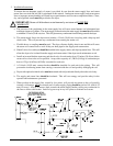
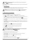
6. Steam Damper Air Piston (Flow Control) Operation Adjustment System
Although the damper operation was tested and adjusted prior to shipping at 80 psi (5.51 bar, 551 kPa),
steam damper operation must be checked before the dryer is put into operation. If damper air adjustment
is necessary, locate flow control valve and make necessary adjustments as noted below.
!