


27
3. Electrical Connections
NOTE: A wiring diagram is included with each dryer and is affixed to the rear upper right guard panel
of the dryer.
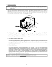
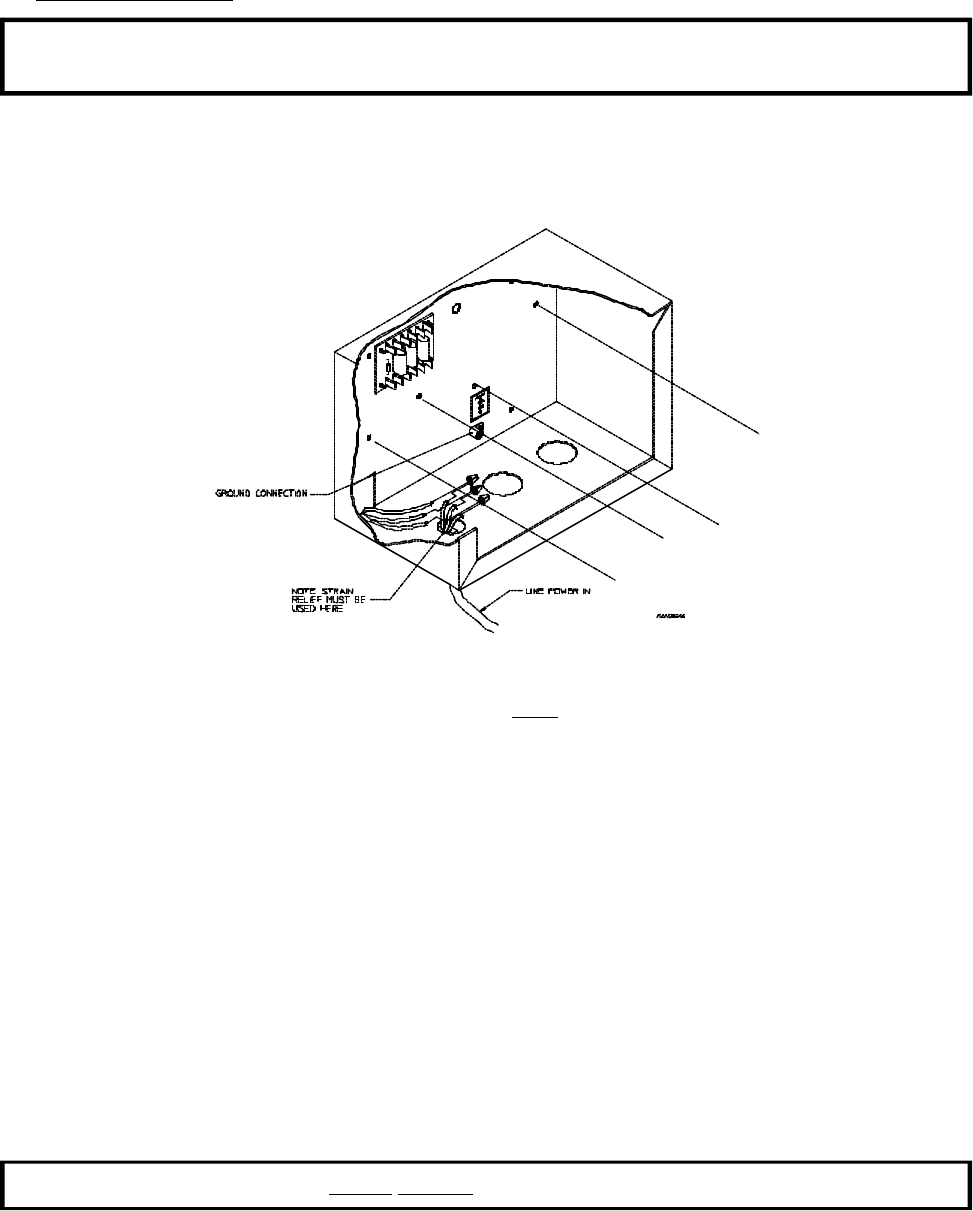
The only electrical input connections to the dryer are the 3-phase (3ø) power leads (L1, L2, and L3),
GROUND, and in the case of 4 wire service, the neutral. These electrical connections are made at the wire
leads located in the electric service and relay box at the rear, upper left hand corner of the dryer. To gain
access into this service box, the service cover must be removed.
Providing local codes permit, power connections to the dryer can be made by the use of a flexible
underwriters laboratory listed cord and pigtail (wire size must conform to rating of the dryer), or the dryer
can be hard wired directly to the service breaker. In ALL cases, a strain relief must be used where the
wires enter the dryer electrical service (relay) box.
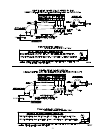
a. Gas Models and Steam Models Dryers
These electrical connections are made at the terminal block located in the electric service/relay box at the
rear, upper left hand corner of the dryer. To gain access into this service box, the service cover (upper
back guard) must be removed.
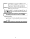
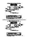
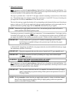
b. Electric Model Dryers
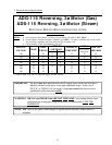
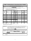
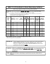
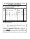
For electric model dryers made to operate at 208 VAC, 230 VAC, or 240 VAC, the electrical input
connection is made into the terminal block located at the upper rear of the dryer. For electric model
dryers made to operate at 380 VAC, 416 VAC, 440 VAC, or 480 VAC, the electrical input connection is
made to the oven relay located at the upper rear of the dryer. Input connection wiring must be sized
properly to handle the dryer's current draw. This information is printed on the dryer's data label which is
affixed to the rear, upper right hand corner of the dryer.
NOTE: A CIRCUIT SERVING EACH DRYER MUST BE PROVIDED.