


© Copyright, Alliance Laundry Systems LLC – DO NOT COPY or TRANSMIT
9
802715
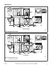
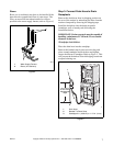
Step 4: (Gas Dryer Only) Connect Gas
Supply Pipe
1. Make certain your dryer is equipped for use with
the type of gas in your laundry room. Dryer is
equipped at the factory for Natural Gas with a
3/8 inch NPT gas connection.
NOTE: The gas service to a gas dryer must
conform with the local codes and ordinances, or in
the absence of local codes and ordinances, with the
latest edition of the National Fuel Gas Code ANSI
Z223.1/NFPA 54 or the CAN/CGA-B149, National
Gas Installation Code.
Natural Gas, 1000 Btu/ft
3
(37.3 MJ/m
3
) service must
be supplied at 6.5 ± 1.5 inch water column pressure.
For proper operation at altitudes above 3000 feet
(915 m) the natural gas valve spud orifice size must be
reduced to ensure complete combustion. Refer to
Table 1.
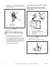
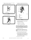
2. Remove the shipping cap from the gas
connection at the rear of the dryer. Make sure you
do not damage the pipe threads when removing
the cap.
3. Connect to gas supply pipe.
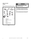
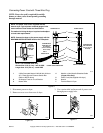
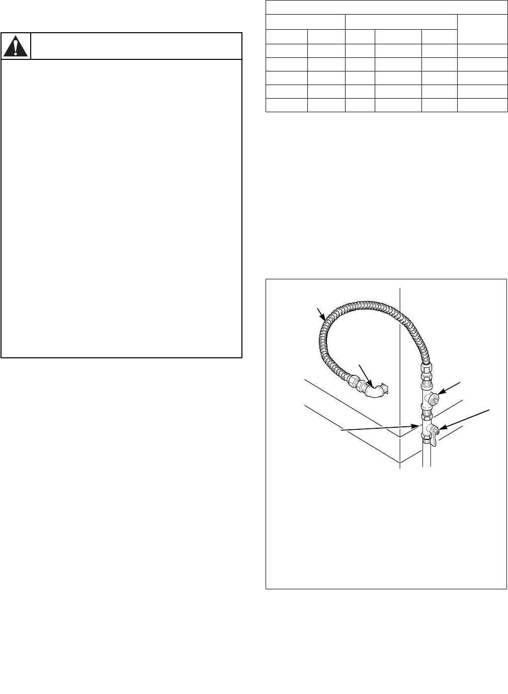
NOTE: When connecting to a gas line, an
equipment shut-off valve must be installed within
6 feet (1.8 m) of the dryer. An 1/8 in. NPT pipe plug
must be installed as shown for checking inlet
pressure. Refer to Figure 8.
4. Tighten all connections securely. Turn on gas and
check all pipe connections (internal & external)
for gas leaks with a non-corrosive leak detection
fluid.
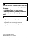
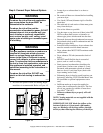
To reduce the risk of gas leaks, fire or
explosion:
• The dryer must be connected to the type
of gas as shown on nameplate located in
the door recess.
• Use a new flexible stainless steel
connector.
• Use pipe joint compound insoluble in L.P.
(Liquified Petroleum) Gas, or Teflon tape,
on all pipe threads.
• Purge air and sediment from gas supply
line before connecting it to the dryer.
Before tightening the connection, purge
remaining air from gas line to dryer until
odor of gas is detected. This step is
required to prevent gas valve
contamination.
• Do not use an open flame to check for gas
leaks. Use a non-corrosive leak detection
fluid.
• Any disassembly requiring the use of
tools must be performed by a suitably
qualified service person.
W316
WARNING
Natural Gas Altitude Adjustments
Altitude Orifice Size
Part No.
feet m No. inches mm
3000 915 43 0.0890 2.26 503778
6000 1830 44 0.0860 2.18 58719
8000 2440 45 0.0820 2.08 503779
9000 2740 46 0.0810 2.06 503780
10,000 3050 47 0.0785 1.99 503781
Table 1
D434I
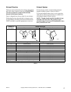
1 New stainless steel flexible connector -
(Use design CSA certified connector)
Use only if allowed by local codes
2 1/8 in. NPT Pipe Plug
3 Equipment Shut-Off Valve
4 Black Iron Pipe Shorter than 20 ft. (6.1 m) -
Use 3/8 in. (9.5 mm) pipe
5 3/8 in. NPT Gas Connection
Figure 8
1
3
2
4
5